Carbon Steel Fastener: Types, Grades, Sizes and Industrial Applications

Carbon Steel Fastener: Types, Grades, Sizes and Industrial Applications

Carbon steel fasteners are widely used in the construction and manufacturing industry to connect parts. In selecting carbon steel fasteners, certain aspects are taken into account, including material grade, strength, size, thread specifics, applicable standards, as well as the environment they will be used in. 

Kalpataru Piping Solution provides carbon steel fasteners to its customers fulfilling the industrial needs according to ASTM and SAE specs. By knowing the kinds of fasteners of carbon steel used and their grades customers will determine the right types of bolts, nuts, washers, and steel rods.

The present guide provides information about applicable ASTM standards including ASTM A307, ASTM A193, and ASTM A194 along with SAE grades of bolts including grade 2, grade 5 and grade 8. The guide also provides information about coatings of carbon steel fasteners, physical properties and dimensions to make right decisions when a customer purchases carbon steel fasteners.

Chemical Composition of Common Fastener Grades

Specification and Grade

Carbon %

Manganese %

Phosphorus % Max

Sulfur % Max

Silicon %

Chromium %

Molybdenum %

ASTM A307 Grade A

0.29 max

1.20 max

0.040

0.150

Not specified

Not specified

Not specified

ASTM A307 Grade B

0.29 max

1.20 max

0.040

0.050

Not specified

Not specified

Not specified

ASTM A193 Grade B7

0.38 to 0.48

0.75 to 1.00

0.035

0.040

0.15 to 0.35

0.80 to 1.10

0.15 to 0.25

ASTM A193 Grade L7

0.37 to 0.49

0.65 to 1.10

0.035

0.040

0.15 to 0.35

0.80 to 1.10

0.15 to 0.25

ASTM A194 Grade 2H

0.40 min

1.00 max

0.040

0.050

0.40 max

Not specified

Not specified

Mechanical Properties

Specification / Grade

Tensile Strength

Yield / Proof Load

Notes

ASTM A307 Grade A

60,000 psi (414 MPa) min

Not specified

General-purpose carbon steel bolts, low/medium strength

ASTM A307 Grade B

60,000 psi (414 MPa) min

Not specified

Flanged joint bolting, general service

ASTM A193 Grade B7

125,000 psi (860 MPa) min

105,000 psi (720 MPa) min

Alloy steel, high-temperature/high-pressure bolting

ASTM A193 Grade L7

125,000 psi (860 MPa) min

105,000 psi (720 MPa) min

Low-temperature service equivalent to B7

ASTM A194 Grade 2H

Proof load per nut size

Heavy hex nuts for use with B7/L7 studs

SAE Grade 2

74,000 psi (510 MPa) min

55,000 psi (379 MPa) proof load

1/4″–3/4″ dia., low/medium carbon steel

SAE Grade 5

120,000 psi (827 MPa) min

85,000 psi (586 MPa) proof load

Medium carbon steel, quenched and tempered

SAE Grade 8

150,000 psi (1,034 MPa) min

120,000 psi (827 MPa) proof load

Alloy steel, quenched and tempered, highest strength

Types of Carbon Steel Fasteners

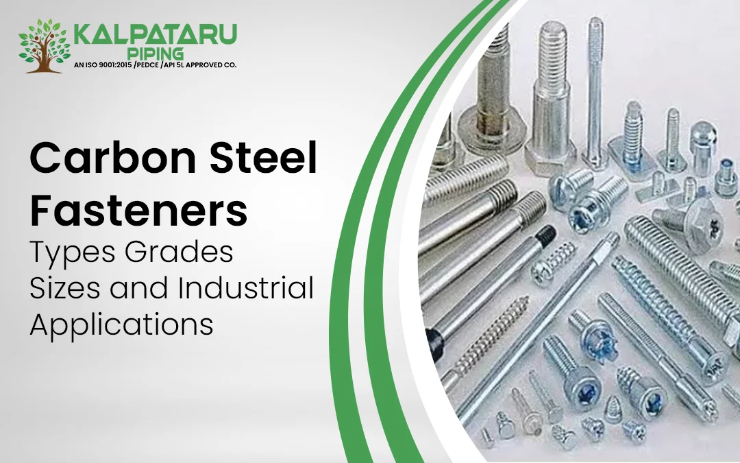
Carbon steel fasteners are available in several forms for structural, mechanical, piping and industrial assembly requirements. The selection depends on joint design, load, size, grade and service conditions.

Carbon Steel Bolts

Carbon steel bolts create strong, removable joints in construction, machinery, piping supports and industrial structures. Grade, diameter, thread and length should match the application.

Carbon Steel Screws

Carbon steel screws are used for joining materials directly through threaded engagement. Machine screws, sheet metal screws and wood screws are selected according to the material and installation method.

Carbon Steel Washers

Carbon steel washers distribute the load beneath a bolt head or nut. They help reduce surface damage and support stable fastening in construction, machinery and automotive assemblies.

Carbon Steel Pins

Carbon steel pins are used to align, locate or secure components. They are commonly found in machinery and mechanical assemblies where accurate positioning is required.

Carbon Steel Nuts

Carbon steel nuts work with compatible bolts and studs to create threaded joints. Hex nuts, heavy hex nuts and lock nuts are selected according to bolt grade, thread and service requirements.

For specifications and sourcing options, exploreKalpataru’s Carbon Steel Fasteners range.

SAE J429 Carbon Steel and Steel Fastener Grades 

SAE J429 is a separate classification system covering mechanical and material requirements for inch series steel bolts, screws, studs, sems and U bolts within its defined scope.

Common SAE J429 grades encountered in general mechanical and automotive fastening include SAE Grade 2, Grade 5 and Grade 8 bolts.

SAE Grade

General Material Basis

Head Marking

Typical Use

Grade 2

Low or medium carbon steel

No radial lines

General purpose mechanical assembly

Grade 5

Medium carbon steel with heat treatment

Three radial lines

Automotive and general industrial assembly

Grade 8

Higher strength alloy steel with heat treatment

Six radial lines

Heavy duty and higher stress mechanical fastening

The head markings help identify the SAE grade of applicable headed fasteners, but buyers should confirm the marking, dimensions, mechanical requirements and material specification against the relevant standard and supplier documentation.

ASTM and SAE Fastener Grades Compared

ASTM and SAE standards identify fastener requirements in different ways. ASTM specifications commonly define requirements for specific product types and service conditions, while SAE J429 establishes mechanical and material requirements for several inch series externally threaded fastener grades.

Standard

Common Grades

Main Focus

Typical Applications

ASTM A307

Grade A, Grade B

Carbon steel bolts and studs for general service

Construction, piping and general fabrication

ASTM A193

B7, L7

High strength alloy steel bolting for elevated or low temperature service

Pressure vessels, piping and industrial equipment

ASTM A194

2H

Nuts for high strength bolting assemblies

Piping, pressure vessels and industrial equipment

SAE J429

Grade 2, Grade 5, Grade 8

Mechanical and material requirements for inch series fasteners

Machinery, automotive and general industrial fastening

This distinction is important when selecting carbon steel bolts because a grade number alone does not identify the complete material specification.

Carbon Steel Fastener Coatings and Corrosion Protection

Carbon steel can require surface protection when exposed to moisture, outdoor conditions or corrosive environments. The coating should be selected according to the service environment rather than added as a generic specification.

Coating or Finish

General Consideration

Typical Environment

Zinc plating

Provides a zinc protective layer for general corrosion protection

Indoor and moderately exposed applications

Hot dip galvanizing

Provides a thicker zinc coating suitable for greater environmental exposure

Outdoor structures and exposed applications

Black phosphate

Provides surface protection and supports suitable lubrication systems

Machinery and general mechanical applications

Xylan or PTFE coating

Low friction and chemical resistance properties can be useful in selected applications

Chemical and specialised mechanical environments

Epoxy coating

Barrier protection can be used where a specified coating system is required

Industrial and exposed applications

Chrome plating

Provides a hard decorative or functional surface where specified

Selected mechanical and appearance driven applications

For related piping requirements, exploreCarbon Steel Buttweld Fittings.

Uses of Carbon Steel Fasteners by Industry

  • Construction: Used for structural steelwork, bridges, buildings, equipment frames and general construction assemblies.
  • Oil and Gas: Used for pipe supports, equipment connections, flanges and maintenance work where specified grades meet service requirements.
  • Automotive: Used in vehicle assemblies, chassis components, engine related parts and mechanical connections.
  • Machinery: Used for joining machine components, housings, frames and fabricated equipment.
  • Piping: Used with piping systems, supports and related equipment where the selected grade meets pressure and temperature requirements. SeeCarbon Steel Buttweld Fittings for related piping components.
  • HVAC and Plumbing: Used for equipment supports, brackets, ductwork and general installation requirements.

For applications involving high carbon steel, the material properties should also be reviewed. SeeProperties and Uses of High Carbon Steel for additional material information. 

How to Choose the Right Carbon Steel Fastener

Selecting the correct carbon steel fastener requires the material grade, mechanical requirements, environment and applicable specification to be considered together.

  1. Confirm the load requirement: Determine the required tensile, shear, proof load and joint strength before selecting the fastener grade.
  2. Confirm the service temperature: Temperature can affect material selection and mechanical performance. High temperature service may require a suitable alloy steel bolting specification rather than a general purpose carbon steel grade.
  3. Select the applicable standard: Determine whether the project requires an ASTM product specification, SAE J429 grade or another applicable standard.
  4. Choose the fastener type: Select bolts, screws, nuts, washers or studs according to the joint design and assembly method.
  5. Confirm the size: Specify diameter, length, thread, head style and mating nut requirements.
  6. Select the coating: Consider moisture, outdoor exposure, marine conditions, chemicals and installation requirements when selecting zinc plating, hot dip galvanizing or another finish.
  7. Check material compatibility: Confirm that the bolt, nut and washer combination is suitable for the selected grade and application.
  8. Review documentation: Where required, request material certificates, inspection reports and applicable test results before shipment.

For broader product requirements, buyers can also review theKalpataru Products range. 
Frequently Asked Questions

What is the difference between ASTM and SAE fastener grades?
ASTM specifications define material, mechanical and manufacturing requirements for specific fastener products. SAE J429 defines mechanical and material requirements for inch series steel bolts, screws, studs and related fasteners.
What does ASTM A193 B7 mean?
ASTM A193 B7 is an alloy steel bolting grade commonly used for high-temperature and high-pressure service. It is used for studs, bolts and other externally threaded fasteners.
Which coating is suitable for outdoor carbon steel fasteners?
Hot dip galvanising provides stronger corrosion protection for many outdoor applications. Zinc plating can suit less severe environments, while coating selection should consider moisture, chemicals, temperature and service conditions.
Can carbon steel fasteners be used with stainless steel components?
They can be used together, but material compatibility should be reviewed. Differences in corrosion potential can contribute to galvanic corrosion, particularly in wet or conductive environments.
What is the difference between carbon steel and alloy steel fasteners?
Carbon steel relies mainly on carbon content for strength and hardness. Alloy steel contains additional alloying elements that can improve strength, toughness, temperature resistance or other service properties.
How should carbon steel fastener sizes be specified?
Specify the applicable standard, grade, diameter, thread type, thread pitch, length, head style, nut requirement, washer requirement and coating. This provides suppliers with the information needed for accurate selection.
Weld Neck Flange vs Slip On Flange: Key Differences, Advantages and Uses

Weld Neck Flange vs Slip On Flange: Key Differences, Advantages and Uses

When you are tasked with selecting between either a weld neck or a slip on flange then it is important to remember that the type of flange considered affects the connection being made and the overall cost. Not only is it true that choosing between a weld neck and a slip on flange impacts which flanges are used but also the pressure and temperature versions used during connection. 

Kalpataru Piping Solutions supply custom flange products as well as standard flanges and operate within the industrial sector. All specifications are catered for including joint design, size of flange selected, and type of flange. This guide compares the two flange types by design, connection method, strength, fatigue considerations, dimensions, cost, standards, and applications. It also provides a practical flange selection guide to help engineers and procurement teams understand where each flange type is commonly specified.

What Is a Weld Neck Flange?

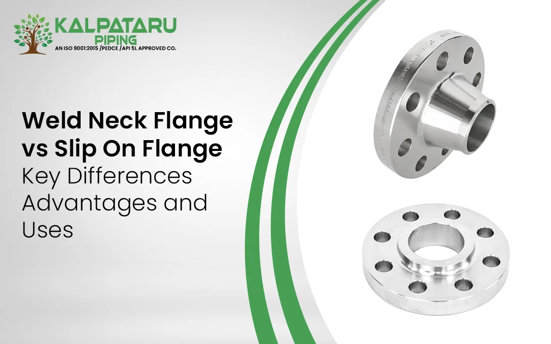
A weld neck flange has a long tapered hub that connects to the pipe through a butt weld. The bore of the flange is machined to match the pipe inside diameter and wall thickness so that the pipe and flange form a continuous internal passage.

The tapered hub is an important part of the design. Instead of placing the main transition directly at the flange face, the gradual change in section helps distribute stresses over a larger area. This makes the design suitable for piping exposed to pressure, temperature changes, vibration, and repeated loading.

The butt weld also provides a direct welded connection between the pipe and flange. Because the joint can be examined using applicable nondestructive examination methods, weld neck flange designs are commonly selected for critical piping where weld quality and stress control are important.

What Is a Slip-On Flange?

A slip on flange has a flat body with a bore that allows the pipe to pass through the flange. The pipe is positioned inside the flange, and the connection is normally completed using fillet welds.

The design makes alignment and installation relatively straightforward and is one reason slip-on flanges are widely used in lower pressure and general utility piping.

For a detailed explanation of slip on flange types, specifications, dimensions, weights, welding, and installation, see Kalpataru’s Complete Guide on Slip On Flanges rather than repeating that information here.

Weld Neck vs Slip On Flange Comparison

The most important differences between the two designs are related to the way the pipe connects to the flange and how loads are transferred through that connection.

Comparison point

Weld Neck Flange

Slip On Flange

Pipe connection

Butt weld

Fillet welds

Weld arrangement

One primary butt weld

Welds on the inside and outside

Hub design

Long tapered hub

Short, flat body

Bore

Matched to pipe bore and wall thickness

A larger bore allows pipe insertion.

Stress distribution

More gradual transition through tapered hub

Higher local stress concentration around the attachment area

Pressure service

Commonly selected for higher-pressure service

Commonly selected for low- and moderate-pressure service

Temperature service

Suitable for demanding temperature conditions when correctly specified

More commonly used for less demanding service

Cyclic loading

Better suited to systems with significant cyclic loading when properly designed

Less suitable where repeated thermal or mechanical cycling governs

Vibration

Suitable for systems where vibration and mechanical loads require stronger flange attachment

Generally used where service conditions are less severe

Weld inspection

Butt welds can be examined using applicable NDE methods.

Two fillet welds require inspection of both attachment welds as specified.

Installation

Requires accurate pipe preparation and butt welding

Generally simpler alignment and installation

Material usage

Usually more material in the hub and flange geometry

Generally lower material cost

Initial flange cost

Usually higher

Usually lower

Common use

Process, power, oil and gas, and critical piping

Utility, water, HVAC, and general piping

Selection basis

Pressure, temperature, fatigue, vibration, and code requirements

Pressure, temperature, cost, and service requirements

There is no universal rule that one flange type should replace the other. The correct selection depends on the design conditions and the applicable piping specification.

Dimensional Comparison between Weld Neck and Slip on flange

Dimensions vary with nominal pipe size and pressure class, so flange dimensions should always be confirmed against the applicable standard and purchase specification.

For comparison, the following Class 150 figures show how the geometry differs for common sizes. The values are based on published ASME B16.5 dimensional tables.

NPS

Flange type

Hub diameter or bore related diameter

Length through hub H

Overall flange thickness B

2

Weld Neck

78 mm

63.6 mm

17.5 mm

2

Slip-On

78 mm

25.6 mm

19.1 mm

4

Weld Neck

135 mm

76.6 mm

23.9 mm

4

Slip-On

135 mm

33.6 mm

23.9 mm

6

Weld Neck

192 mm

88.6 mm

25.5 mm

6

Slip-On

192 mm

39.6 mm

25.5 mm

The dimensional data shows an important difference in geometry. At these Class 150 sizes, the flange thickness is the same or very similar between the two designs, while the weld neck flange has a substantially longer hub section.

For example, the published Class 150 data gives a 63.6 mm H dimension for an NPS 2 weld neck flange compared with 25.6 mm for the slip-on design. At NPS 6, the corresponding dimensions are 88.6 mm and 39.6 mm.

What Does Each Flange Type Cost to Install?

Initial purchase price is often one of the first factors considered during flange selection, but the flange price alone does not represent the complete installed cost.

Cost factor

Weld Neck Flange

Slip On Flange

Flange purchase cost

Usually higher

Usually lower

Material quantity

Usually higher

Usually lower

Pipe preparation

More precise

Generally simpler

Welding

Butt welding

Fillet welding

Welding time

Depends on size and wall thickness

Depends on size and weld requirements

Inspection

Based on applicable weld examination requirements

Based on applicable weld examination requirements

Fabrication complexity

Higher

Lower

Suitability for demanding service

Commonly preferred

More limited depending on design

Total installed cost

Must include fabrication and inspection

Must include fabrication and inspection

The final cost difference therefore depends on size, pressure class, material, quantity, welding procedure, inspection requirements and project location. A lower flange purchase price does not automatically mean a lower total project cost.

Flange Selection Guide

The following table provides a practical starting point when comparing a weld neck vs slip on flange.

Application or condition

Common choice

Reason

Refinery process piping

Weld Neck

Better suited to demanding process conditions

Chemical process piping

Weld Neck

Useful where pressure, temperature and fluid service are demanding

Oil and gas process piping

Weld Neck

Common choice for higher integrity connections

Power plant steam piping

Weld Neck

Suitable for demanding temperature and pressure conditions

High pressure process line

Weld Neck

Stronger connection geometry and butt weld

Cyclic thermal service

Weld Neck

Better suited to repeated thermal loading

High vibration service

Weld Neck

Appropriate where connection stresses require greater attention

Hazardous process fluid

Weld Neck

Commonly specified for critical piping connections

Cooling water

Slip On or Weld Neck

Depends on pressure, temperature and project specification

HVAC piping

Slip On

Often suitable for utility service

General water service

Slip On

Simple installation where permitted

Water treatment piping

Slip-On or Weld Neck

Selection depends on design conditions

Low-pressure utility piping

Slip On

Lower material and installation costs can be useful.

Large-diameter low pressure water main

Slip On

Can provide a practical, lower-cost connection

Temporary or infrequently used piping

Slip On

Simpler installation can be an advantage.

This is a selection guide rather than a substitute for engineering design. Pressure, temperature, pipe material, fluid service, corrosion allowance, fatigue, welding requirements and the governing code should all be considered before final selection.

Materials and Standards for Flange Selection

Material selection is an important part of any flange selection guide and should consider fluid, pressure, temperature, corrosion conditions, and the applicable code. Kalpataru supplies weld neck flanges in carbon steel, alloy steel, stainless steel, duplex, super duplex, copper, and nickel alloys, including Nickel 200,Monel 400, Inconel 600, Inconel 625 and Hastelloy C276. Its slip on flangesinclude carbon steel, alloy steel, stainless steel, duplex, super duplex, nickel alloys, copper alloys and titanium. Common grades include ASTM A105 and ASTM A182 F5, F9, F11, F22 and F91. For carbon steel requirements, see the ASTM A105 Flange Manufacturerpage. ASME B16.5 flanges cover NPS 1/2 to NPS 24 and define ratings, materials, dimensions, tolerances, marking and testing.

Frequently Asked Questions

What is the main difference between a weld neck and a slip-on flange?
A weld neck flange has a tapered hub and connects to the pipe through a butt weld. A slip-on flange has a simpler body that fits over the pipe and is normally attached using fillet welds. Weld neck flanges are commonly selected for more demanding pressure, temperature, cyclic loading, and vibration conditions, while slip-on flanges are often used in lower pressure and utility applications.
Can a slip-on flange be used for high-pressure service?
A slip-on flange can be used only where the applicable design code, pressure temperature rating, and project specification permit it. For demanding high-pressure applications, a weld neck flange is often considered because of its connection geometry and stress distribution characteristics.
Why does a weld neck flange have a tapered hub?
The tapered hub provides a gradual transition between the flange body and the pipe. This helps distribute stresses more gradually and reduces the abrupt geometric change found at a simpler flange attachment.
Is a slip-on flange cheaper than a weld neck flange?
A slip-on flange is generally less expensive to purchase because its geometry uses less material and its installation can be simpler. However, the total installed cost also depends on welding, inspection, fabrication, material, quantity, and project requirements.
What standard governs flange dimensions?
ASME B16.5 is a key standard for pipe flange dimensions, pressure temperature ratings, materials, tolerances, marking, and testing for its specified size and pressure ranges. Other standards can apply depending on the flange type, size, pressure system, and project requirements.
Which flange should be selected for process piping?
The selection depends on the design pressure, temperature, fluid service, pipe material, cyclic loading, vibration, applicable piping code, and project piping specification. Weld neck flanges are commonly considered for demanding process service, while slip-on flanges may be suitable for less demanding services where permitted by the design.
Inconel 625 Round Bar Properties, Grades, Sizes and Industrial Applications

Inconel 625 Round Bar Properties, Grades, Sizes and Industrial Applications

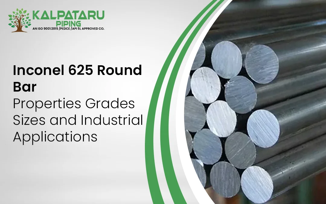
The Inconel 625 round bar is a bar made from a nickel-based chromium-molybdenum-niobium alloy that is used in applications where corrosion resistance and strength and reliable performance are paramount in challenging operating environments. The governing material specification for round bars and rods is ASTM B446, with a corresponding ASME specification ABME SB446.

Kalpataru Piping Solutions supplies Inconel 625 round bars in various forms and sizes to serve various industrial purposes. This guide aims to explain Inconel 625 – its chemical composition, mechanical properties, (UNS N06625), its constituents, state, sizes available, how to calculate the weights of Inconel 625 and its applications so as to provide accurate information for engineers, consumers, and purchasing department for their understanding of the specification prior to making an order. 

What Is an Inconel 625 Round Bar?

Inconel 625 is a nickel-based chromium-molybdenum-niobium alloy represented by UNS N06625. Its European material number is 2.4856. The alloy is characterized by the combination of nickel and chromium, together with the considerable amounts of molybdenum and niobium, which bestows it with a high resistance to various corrosive environments, in addition to good properties.

Round bar means a solid circular section manufactured in straight lengths. According to ASTM B446 the alloy UNS N06625 comes in several different heat-treated forms. The chosen condition defines both strength and ductility of the alloy and its intended application.

The larger range of Inconel Round Bar range might help a customer in selecting proper grades when comparing Inconel 600, Inconel 625 and Inconel 718.

Inconel 625 Chemical Composition

Element

Composition

Nickel

58.0 percent minimum

Chromium

20.0 to 23.0 percent

Molybdenum

8.0 to 10.0 percent

Niobium plus Tantalum

3.15 to 4.15 percent

Iron

5.0 percent maximum

Cobalt

1.0 percent maximum

Manganese

0.50 percent maximum

Silicon

0.50 percent maximum

Carbon

0.10 percent maximum

Phosphorus

0.015 percent maximum

Sulfur

0.015 percent maximum

Aluminium

0.40 percent maximum

Titanium

0.40 percent maximum

The exact chemical composition should always be checked against the material test certificate supplied for the actual heat. ASTM B446 specifies chemical requirements for UNS N06625 and also covers dimensional and mechanical requirements for the applicable product condition.

Inconel 625 Mechanical Properties

ASTM B446 Condition

Size

Tensile Strength Minimum

Yield Strength Minimum

Elongation Minimum

Grade 1 Annealed

Up to 102 mm

827 MPa

414 MPa

30 percent

Grade 1 Annealed

Over 102 to 254 mm

758 MPa

345 MPa

25 percent

Grade 2 Solution Annealed

All sizes

690 MPa

276 MPa

30 percent

Grade 3 Solution Annealed and Cold Worked

Up to 63 mm

930 MPa

690 MPa

25 percent

These indicators illustrate the requirement that the condition is essential in the purchase specification. Buyers ordering Inconel 625 Round Bar should indicate the required ASTM B446 grade and ask for the EN 10204 3.1 material test certificate in situations where traceability is needed.

Standard Specifications and Equivalent Grades

ASTM B166 has been widely misapplied when discussing Inconel 625 bars. The standard actually applies to nickel-chromium-iron alloys, including Inconel 600. The correct standard when specifying Inconel 625 bars and rods is ASTM B446 and if an ASME standard is required, ASME SB446 should be referenced. 

Inconel 625 Equivalent Grades

Standard or System

Designation

UNS

N06625

Werkstoff Number

2.4856

JIS

NCF 625

BS

NA 21

EN

NiCr22Mo9Nb

DIN

2.4856

AFNOR

NC22DNB4M

Equivalent designations help when comparing international material specifications, but they should not be treated as automatic permission to substitute one specification for another. Project specifications, design codes and purchaser requirements should be checked before making a substitution.

Approximate Weight Reference

The theoretical weight of a solid round bar can be estimated using its diameter and material density. Inconel 625 has a density of approximately 8.44 g/cm³.

Diameter

Approximate Weight per Metre

10 mm

0.66 kg

20 mm

2.65 kg

25 mm

4.14 kg

50 mm

16.57 kg

75 mm

37.29 kg

100 mm

66.29 kg

Actual supplied weight can vary because of dimensional tolerance, length tolerance and finishing operations. Buyers requiring exact shipment weight should use the dimensions and certified material details for the supplied bar

Inconel 625 Industrial Applications 

  • Oil and Gas: Used for components exposed to aggressive fluids, elevated temperatures and chloride containing offshore environments.
  • Marine and Shipbuilding: Suitable for selected components exposed to seawater and chloride environments where corrosion resistance is important.
  • Aerospace: Used for exhaust components, ducting and other parts requiring strength and corrosion resistance. Aerospace projects may specify AMS 5666. SeeInconel 718 Round Bar for another nickel alloy option.
  • Chemical Processing: Suitable for equipment exposed to acids, chlorides and other corrosive media.
  • Nuclear and Power Generation: Used for selected components requiring corrosion resistance and mechanical performance under demanding service conditions.
  • Pulp and Paper: Used in equipment exposed to corrosive and elevated temperature conditions. SeeInconel Round Bars in the Pulp and Paper Industry

How to Select the Right Inconel 625 Round Bar

Selecting an Inconel 625 round bar should consider the service environment, applicable standard and material condition. Evaluate temperature, pressure and corrosion exposure before selecting ASTM B446 or ASME SB446. Choose the required annealed, solution annealed or cold worked condition based on mechanical requirements. Then specify diameter, length, tolerance and surface finish. Finally, define inspection requirements such as chemical analysis, tensile testing, hardness testing, dimensional inspection and an EN 10204 3.1 MTC. This approach helps ensure the selected bar meets the application, dimensional and documentation requirements.

Frequently Asked Questions

What standard governs Inconel 625 round bars?
ASTM B446 specifies UNS N06625 rod and bar. ASME SB446 is the corresponding ASME specification used where applicable.
What is the difference between Inconel 625 and Inconel 718 round bars?
Inconel 625 is a nickel-based alloy known for corrosion resistance, while Inconel 718 is a precipitation-hardened alloy developed for higher-strength applications.
What does the UNS number N06625 mean?
UNS N06625 is the Unified Numbering System designation for Inconel 625. The alloy is also identified by Werkstoff number 2.4856.
What sizes are available for Inconel 625 round bars?
Inconel 625 round bars are available in various diameters, lengths, and conditions. Exact sizes depend on the manufacturing method and supplier capability and should be confirmed before ordering.
Can an Inconel 625 round bar be welded?
Yes, Inconel 625 can be welded using suitable procedures and compatible filler materials. Welding requirements should be established according to the application and applicable specification.
Why should buyers request an MTC for an Inconel 625 round bar?
An MTC documents chemical composition and applicable mechanical test results for the supplied heat, helping buyers verify material compliance with the specified grade and standard.

Aluminium Perforated Sheet Types, Sizes, Thicknesses and Applications

Aluminium Perforated Sheet Types, Sizes, Thicknesses and Applications

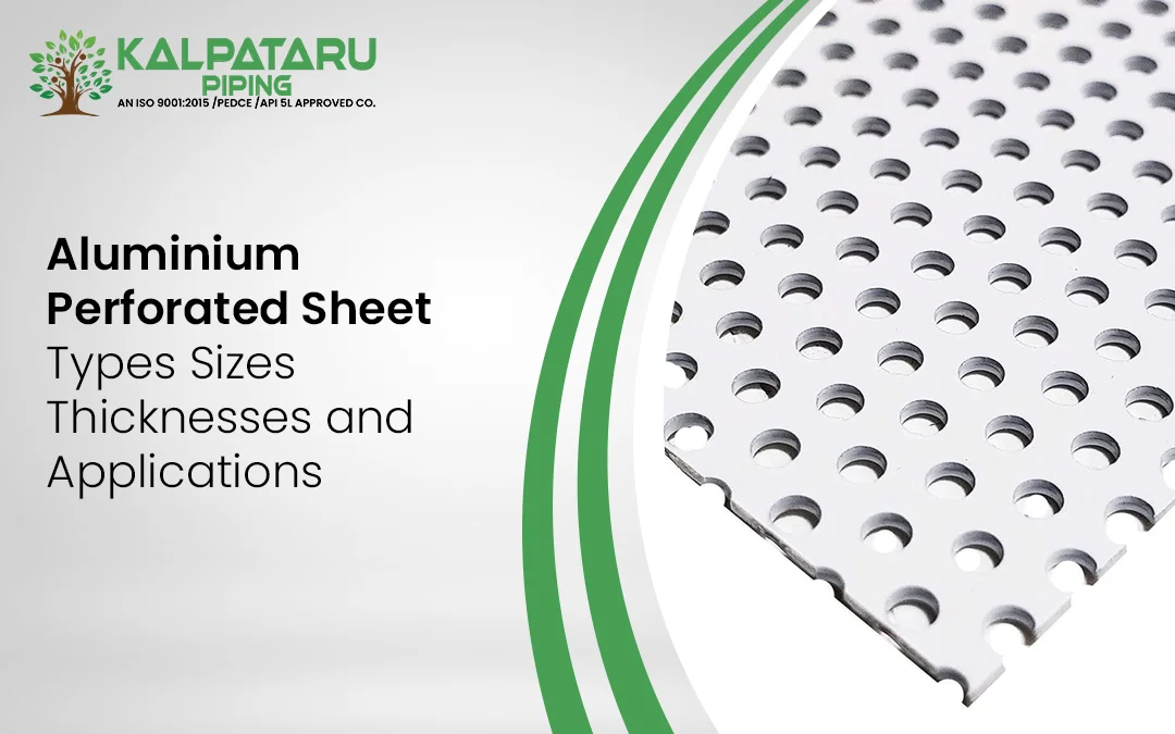
Aluminium perforated sheets are flat sheets of aluminium with a specific arrangement of holes. The holes can be geometric shapes such as circular, square, rectangular, and hexagonal, or can be customized according to the needs of the users. The combination of aluminium and regulated perforation makes these sheets useful for construction, ventilation, machine protection, screening, ceiling, shading, and other practical purposes.

Kalpataru Piping Solutions was founded in 2015 and is a certified ISO 9001:2015 manufacturer, producer, distributor, and exporter of metal products. The company offers its clients a wide array of piping products, both metallic and non-metallic, for various industrial and engineering applications.

This article aims to inform readers about the types, sizes, thicknesses, and functionalities of aluminium perforated sheets. It also explains the meaning of terms such as perforation size and pitch and their impact on the area of a particular project.

What Is Aluminium Perforated Sheet?

Aluminium perforated sheet is a flat aluminium sheet containing a regular arrangement of holes or openings. The openings are created by punching, stamping, or controlled cutting according to a specified hole shape, size and spacing.

Round holes are widely used for general ventilation, screening, and architectural applications. Square, slotted, hexagonal and decorative patterns can be selected when the project requires a different airflow characteristic, appearance or screening effect.

The manufacturing process also affects the final specification. Mechanical punching is commonly used for standard patterns and production quantities, while CNC or laser cutting can be considered for special shapes, decorative designs and customised layouts.

A perforated aluminium sheet is normally specified using the aluminium grade, temper where required, thickness, hole shape, hole diameter, pitch, pattern arrangement, open area, sheet dimensions and surface finish.

Sizing and Standard Dimensions

The available size of an aluminium perforated sheet depends on the base sheet, perforation pattern, thickness, production equipment and project requirement. Common sheet dimensions used in the market include both metric and imperial formats.

Common Sheet Size Approximate Imperial Size Typical Consideration
1000 x 2000 mm Approximately 3.3 x 6.6 ft General fabrication and industrial panels
1220 x 2440 mm 4 x 8 ft Common architectural and industrial size
1250 x 2500 mm Approximately 4.1 x 8.2 ft Larger panel applications
1500 x 3000 mm Approximately 5 x 9.8 ft Larger architectural and industrial panels
Custom size According to the requirement Projects requiring reduced fabrication waste

For buyers who need general aluminium sheet information, Kalpataru also provides information onAluminium Plates and Sheets. The present guide focuses specifically on perforated aluminium sheet selection.

Types of Aluminium Perforated Sheet

Aluminium perforated sheet is available in different patterns based on the shape and arrangement of the openings. The selected pattern depends on open area, airflow, visibility, appearance and application requirements.

Round Hole Aluminium Perforated Sheet

Round Hole Aluminium Perforated Sheet

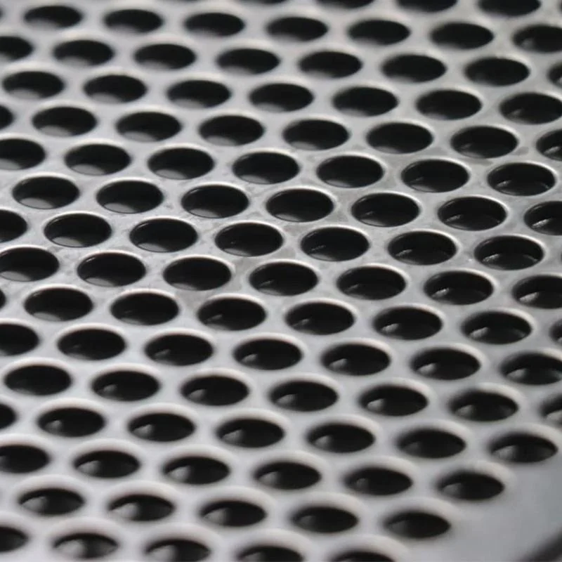
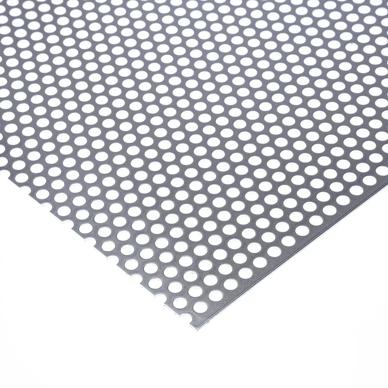
Round holes are widely used and can be arranged in straight or staggered patterns. They are specified by hole diameter and pitch and are suitable for ventilation panels, machine guards, screens, equipment covers and architectural applications.

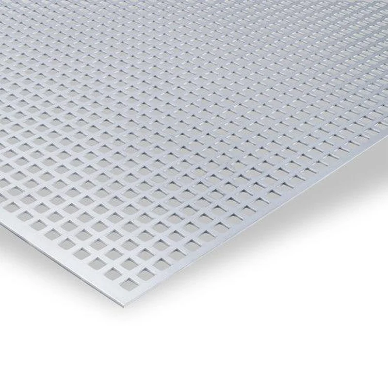
Square Hole Aluminium Perforated Sheet

Square Hole Aluminium Perforated Sheet

Square openings provide a uniform geometric appearance and can be selected for equipment panels, screens, guards and decorative applications where pattern consistency is important.

Slotted Aluminium Perforated Sheet

Slotted Aluminium Perforated Sheet

Slotted sheets use elongated openings with defined slot length, width and spacing. They are commonly considered for ventilation panels, grilles, screens and architectural features.

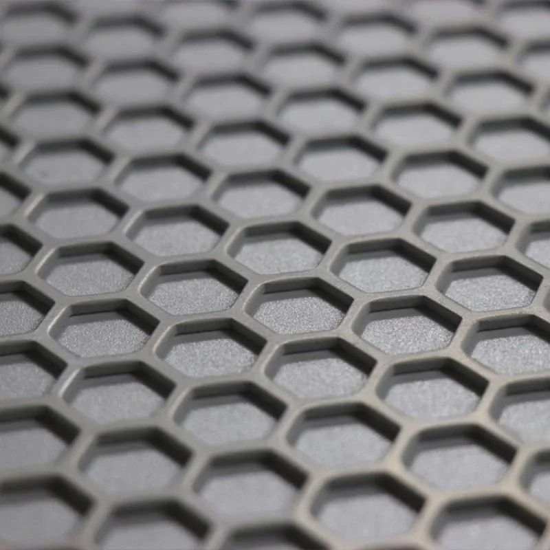
Hexagonal Aluminium Perforated Sheet

Hexagonal Aluminium Perforated Sheet

Hexagonal openings create a distinctive repeating pattern and can provide a relatively high open area. They are used for ventilation panels, equipment covers, decorative screens and architectural applications.

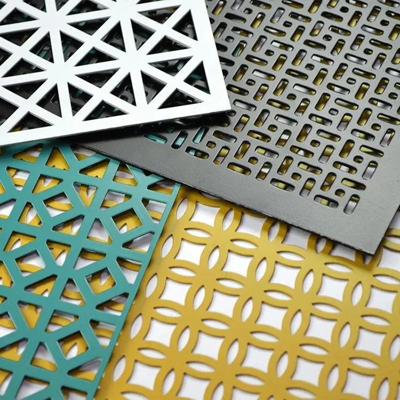
Custom Aluminium Perforated Sheet

Custom Aluminium Perforated Sheet

Custom patterns can be specified for particular project requirements. The enquiry should include aluminium grade, temper, thickness, sheet size, hole shape, opening dimensions, pitch, pattern, and finish.

Aluminium Perforated Sheet Thickness and Classification

Thickness is one of the most important factors when selecting aluminium perforated sheet. A thinner sheet can reduce weight and may be suitable for decorative applications, while a thicker sheet can provide greater rigidity for equipment covers, industrial screens and fabricated panels.

A useful general classification is shown below.

Thickness Range

General Classification

Typical Consideration

0.15 to 2.0 mm

Thin sheet

Decorative panels, interior screens, acoustic applications and lightweight covers

2.0 to 6.0 mm

Conventional sheet

Facades, ceilings, ventilation panels and general industrial applications

6.0 to 25 mm

Medium thickness

Heavy duty screening and fabricated industrial components

Above 25 mm

Thick material

Special engineering requirements subject to material and fabrication capability

These categories are general selection guidelines rather than universal industry classifications. The actual thickness should be selected according to the required load, span, support arrangement, fabrication method, hole pattern and application.

Understanding Open Area Percentage

Open area percentage is the proportion of the total aluminium perforated sheet surface occupied by holes. It is mainly determined by the hole size, pitch and perforation pattern. A higher open area generally allows greater airflow and light transmission, while a lower open area leaves more metal between the openings and can provide greater screening or privacy.

As a general selection guide:

Open Area

General Consideration

Typical Applications

Below 25%

Lower airflow and visibility with more solid sheet area

Structural screening, privacy panels and decorative applications

25% to 50%

Balanced airflow, visibility and screening

General ventilation, equipment screens and architectural panels

Above 50%

Higher airflow and light transmission

Acoustic applications, ventilation and filtration related uses

These ranges are general guidelines rather than universal classifications. The required open area should be selected according to airflow, visibility, light transmission, acoustic requirements, structural considerations and the specified hole pattern.

Common Aluminium Grades Used for Perforated Sheet

Common grades considered for aluminium sheet applications include 1100, 3003, 5052 and 6061.

Aluminium Grade

General Characteristics

Typical Considerations

1100

High aluminium content and good formability

General sheet applications and applications where forming is important

3003

Aluminium manganese alloy with good formability

General engineering, architectural and fabricated panels

5052

Aluminium magnesium alloy with good corrosion resistance

Marine, outdoor and fabricated applications

6061

Aluminium magnesium silicon alloy with higher strength

Structural and engineering applications where greater strength is required

The exact grade and temper should be confirmed against the applicable material specification and project requirements.

Chemical Composition of Common Aluminium Grades

Element

Aluminium 1100

Aluminium 3003

Aluminium 5052

Aluminium 6061

Silicon, Si

0.95 max*

0.60 max

0.25 max

0.40 to 0.80

Iron, Fe

0.95 max*

0.70 max

0.40 max

0.70 max

Copper, Cu

0.05 to 0.20

0.05 to 0.20

0.10 max

0.15 to 0.40

Manganese, Mn

0.05 max

1.00 to 1.50

0.10 max

0.15 max

Magnesium, Mg

0.05 max

0.05 max

2.20 to 2.80

0.80 to 1.20

Chromium, Cr

0.05 max

0.05 max

0.15 to 0.35

0.04 to 0.35

Zinc, Zn

0.10 max

0.10 max

0.10 max

0.25 max

Titanium, Ti

0.05 max

0.05 max

0.15 max

0.15 max

Aluminium, Al

99.00 min

Remainder

Remainder

Remainder

For Aluminium 1100, silicon and iron are commonly controlled together with a combined maximum limit of 0.95% rather than being treated as two independent maximum values. 

Mechanical Properties of Common Aluminium Grades

Grade and Temper

Tensile Strength, MPa

Yield Strength, MPa

Elongation, %

Typical Use in Perforated Sheet

1100 O

90

35

35

Formable panels and general applications

1100 H14

125

115

9

General fabricated and architectural panels

3003 O

110

40

30

Formed panels and general applications

3003 H14

150

145

8

Ventilation panels, screens and fabricated panels

5052 O

195

90

25

Formed panels and corrosion exposed applications

5052 H32

260

215

10

Outdoor panels, screens and equipment covers

6061 O

125

55

25

Formable engineering applications

6061 T6

310

275

12

Higher strength engineering panels

Manufacturing Process and Surface Finishes

Aluminium perforated sheet is produced using mechanical punching, stamping, CNC or laser cutting. Mechanical punching suits standard patterns and higher production volumes, while CNC or laser cutting supports decorative, complex and customised designs. The selected process depends on hole geometry, sheet thickness, quantity and dimensional accuracy.

Common finishes include mill, anodized, powder coated and painted finishes. Anodizing improves surface durability and appearance, while powder coating provides colour options and additional surface protection. The finish should be selected based on the installation environment, appearance requirements and fabrication process.

Does Aluminium Perforated Sheet Have a Working Pressure Rating?

Aluminium perforated sheet should not automatically be treated as a pressure rated component.

The presence of holes changes the effective section of the material and the structural behaviour of the panel. A pressure-containing application therefore requires a separate engineering assessment based on the material, thickness, perforation pattern, dimensions, support arrangement, temperature, and design pressure.

For pressure containing equipment, the applicable equipment design code and project specification should take precedence over a general perforated sheet specification.

Standards, Inspection, and Material Documentation 

Aluminum perforated sheets are normally defined in regard to their standards, the standards referring to compositions, mechanical features and the dimensions of the aluminum. ASTM B209 determines aluminum and aluminum alloy sheet and plate while EN 485 contains specifications regarding aluminum and aluminum alloy sheets, strips and plates. EN 573 provides the definition of the chemical composition and designation of wrought aluminum and aluminum alloys while JIS H4000 treats aluminum and alloyed aluminum sheets, plates and strips used for industrial purposes.

A typical material verification process may include:

Inspection Item

Purpose

Chemical composition

Confirms the supplied aluminium grade

Mechanical testing

Confirms specified mechanical properties

Thickness measurement

Confirms sheet thickness

Sheet dimensions

Confirms width and length

Hole diameter

Confirms perforation size

Pitch measurement

Confirms opening spacing

Visual inspection

Checks surface and manufacturing condition

Material traceability

Connects the material to the relevant heat or batch documentation

How to Select the Right Aluminium Perforated Sheet

Selecting the right aluminium perforated sheet starts with defining the application. First, identify whether it is required for ventilation, screening, privacy, decoration, filtration, acoustic treatment or equipment protection. Next, determine the required open area for airflow, visibility and light transmission. Choose the hole pattern based on functional and visual requirements. Select the aluminium grade according to the service environment and corrosion exposure. Finally, specify the sheet thickness, dimensions, hole diameter, pitch, pattern arrangement, surface finish and fixing method. This ensures the sheet is selected for performance rather than appearance alone.

Frequently Asked Questions

What is aluminium perforated sheet used for?
Aluminium perforated sheet is used for ventilation panels, architectural screens, facade panels, sunshades, equipment covers, machine guards, acoustic panels, filtration and decorative applications. The correct grade, thickness, hole pattern and open area depend on the intended use.
Which aluminium grade is commonly used for perforated sheet?

Grades such as 1100, 3003, 5052 and 6061 can be considered for aluminium sheet applications. The correct grade depends on strength, formability, corrosion exposure, fabrication requirements and the project specification.

What thickness is available in aluminium perforated sheet?
The required thickness depends on the aluminium grade, perforation pattern, panel dimensions and application. Commercial availability varies by supplier and pattern. Buyers should specify the required thickness rather than assuming that every hole pattern is available in every thickness.
What are the common aluminium perforated sheet hole patterns?

Common patterns include round, square, slotted and hexagonal openings. Custom patterns can also be specified when a project requires a particular appearance, open area or functional requirement.

What is open area in perforated sheet?
Open area is the percentage of the total sheet surface occupied by the openings. It is influenced by the hole size and pitch. Open area is important when the sheet is being used for ventilation, screening, airflow or light control.
What is the difference between hole diameter and pitch?
Hole diameter is the size of a circular opening. Pitch is the distance between adjacent holes according to the specified pattern. Both dimensions influence the open area and the amount of metal remaining between the openings.

Inconel Temperature Resistance Chart for All Grades

Inconel Temperature Resistance Chart for All Grades

The most important thing about Inconel from a specs point of view is its ability to maintain strength and resist oxidation at high enough temperatures that would otherwise cause other stainless steels to become soft or scale. one heat limit. Grade 625 tops out well below grade 601. The chart below lines up the maximum service temperature for every Inconel and Incoloy grade Kalpataru Piping supplies, so you can shortlist a grade for a spec or RFQ in one pass. For the fuller picture on composition, general properties, and melting point, start with our Inconel material grades, properties, and composition guide, then come back here for the temperature-specific comparison.

Inconel Maximum Service Temperature: All Grades (Master Chart)

Grade

UNS No.

Approx. Max Continuous Service Temp

Notes

Inconel 600

N06600

Up to ~1,000–1,150°C (oxidation); high strength retained to ~650°C

Strength and oxidation limits differ; see “Why Different Sources Quote Different Max Temperatures” below

Inconel 601

N06601

Up to ~1,090–1,150°C

Excellent oxidation resistance; good creep strength above 500°C

Inconel 617

N06617

Up to ~1,100°C

High-temperature strength and oxidation resistance

Inconel 625

N06625

~980°C (continuous service) / up to 1,093°C (strength retention, per source)

See “Why Different Sources Quote Different Max Temperatures” for why figures vary by source

Inconel 690

N06690

Effective to ~1,000°C+

Chosen mainly for chloride and high-temperature water SCC resistance

Inconel 718

N07718

Good strength and toughness up to ~650–700°C

Precipitation-hardened; loses strength above this range

Inconel X-750

N07750

Good strength below ~980°C

Common in springs, fasteners, gas turbine components

Incoloy 800 / 800H / 800HT

N08800 / N08810 / N08811

Strength maintained above ~600°C; oxidation-resistant to ~1,100°C

800H/800HT variants improved for creep service

Incoloy 825

N08825

General service typically below ~550°C

Selected for corrosion resistance, not high-temperature strength


Strength Retention vs Temperature (Inconel 600 and 625)

A max temperature figure only tells you when a grade starts to fail. It does not tell you how much strength you still have at 400°C versus 700°C, which is the number that actually drives a wall-thickness or fastener-torque calculation. The table below tracks tensile and yield strength across five temperature points for Inconel 600, and flags where the same data needs to be pulled for Inconel 625.

Temp (°C)

Inconel 600 Tensile (MPa)

Inconel 600 Yield (MPa)

Inconel 625 Tensile (MPa)

Inconel 625 Yield (MPa)

316

624

214

See mill certificate / ASTM B446

See mill certificate / ASTM B446

427

609

203

See mill certificate / ASTM B446

See mill certificate / ASTM B446

538

579

183

See mill certificate / ASTM B446

See mill certificate / ASTM B446

649

448

117

See mill certificate / ASTM B446

See mill certificate / ASTM B446

760

103

28

See mill certificate / ASTM B446

See mill certificate / ASTM B446

Frequently Asked Questions

What is the maximum temperature Inconel can withstand?

Depending on the grade, Inconel can withstand temperatures from about 650°C to over 1,100°C.

Which Inconel grade has the highest temperature resistance?

Inconel 601 and Incoloy 800HT are suitable for continuous service above 1,100°C in oxidizing conditions.

What is the difference between Inconel 625 and Inconel 718 in terms of temperature limits?

Inconel 625 can handle around 980°C, while Inconel 718 is generally limited to approximately 650–700°C.

Why do different sources give different maximum temperatures for the same Inconel grade?

Because temperature limits depend on oxidation resistance, strength retention, and continuous or intermittent service.

At what temperature does Inconel 718 lose its strength?

Inconel 718 generally maintains good strength up to around 650–700°C, after which its strength decreases.

Is Inconel better than stainless steel at high temperatures?

Yes, Inconel generally provides better high-temperature strength and oxidation resistance than standard stainless steel grades such as 304 and 316.

Can Inconel 600 be used continuously above 1,000°C?

Yes, Inconel 600 can provide oxidation resistance above 1,000°C, although its load-bearing strength is lower at these temperatures.

Which Inconel grade should I choose for a furnace or heat exchanger application?

For furnaces, Inconel 601 or Incoloy 800HT are suitable for high temperatures. For corrosive heat-exchanger service, Inconel 625 or Incoloy 825 may be preferred.

Duplex 2205 vs Super Duplex 2507: Key Differences and How to Choose

Duplex 2205 vs Super Duplex 2507: Key Differences and How to Choose

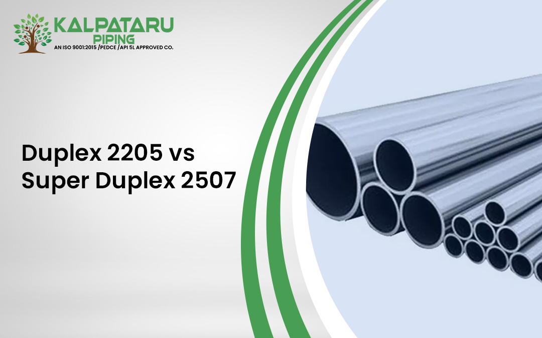
Duplex 2205 and Super Duplex 2507 are on the same spec sheet for pressure vessels, offshore piping, seawater systems, and the choice between them really comes down to one question: how much chloride exposure.The duplex workhorse is 2205, the one sold and priced for use in moderate-chloride and general industrial applications. The 2507 is more expensive, but provides real headroom where seawater, subsea, and high pressure are involved where there is no room for pit or crevice failure. The tables below provide you with the composition, PREN, mechanical, standards and welding data you need. The Duplex stainless steel 2205 to 2507 comparison is the most direct of our comparison posts, but if you aren’t already familiar with what duplex stainless steel is and how the grade family is divided, take the time to read our guide to duplex stainless steel first.

What Is Duplex 2205?

Duplex stainless steel commonly utilized in industry includes the Duplex 2205 (UNS S32205/S31803), which consists of almost equal amounts of ferrite and austenite. That mixed structure gives it close to double the yield strength of the common 300-series austenitic stainless steels It is the most preferred steel until it is surpassed by the operational environment due to its easy availability and low cost. Duplex 2205 is available in various forms from Kalpataru Piping.

What Is Super Duplex 2507?

Super Duplex 2507 (UNS S32750), on the other hand, uses the same two-phase metallurgy but goes one step ahead with alloying elements – higher amounts of chromium, molybdenum, and nitrogen when compared with the 2205 alloy, resulting in improved resistance to pitting and crevice corrosion in environments having high chloride content, and an increased strength. This increased margin comes at a higher cost, and it is also not easy to weld and machine. Therefore, the Super Duplex 2507 is used only where there is really tough service requirement and not just as a general replacement to 2205.

Chemical Composition: Duplex 2205 vs Super Duplex 2507

The difference starts with alloy content. 2507 carries meaningfully more chromium, molybdenum, and nitrogen than 2205, and that gap is what drives every other difference on this page.

Element Duplex 2205 (S32205 / S31803) Super Duplex 2507 (S32750)
Carbon (C) max 0.030 0.030
Manganese (Mn) max 2.00 1.20
Silicon (Si) max 1.00 0.80
Phosphorus (P) max 0.030 0.035
Sulfur (S) max 0.020 0.020
Chromium (Cr) 22.0 to 23.0 24.0 to 26.0
Nickel (Ni) 4.5 to 6.5 6.0 to 8.0
Molybdenum (Mo) 3.0 to 3.5 3.0 to 5.0
Nitrogen (N) 0.14 to 0.20 0.24 to 0.32
Copper (Cu) max not specified 0.50


PREN and Corrosion Resistance of Duplex 2205 vs Super Duplex 2507

Grade Midpoint Cr / Mo / N used Calculated PREN Typical published range
Duplex 2205 22.5 / 3.25 / 0.17 approximately 36 34 to 38
Super Duplex 2507 25.0 / 4.0 / 0.28 approximately 43 40 to 45


Mechanical Properties of Duplex 2205 vs Super Duplex 2507

Both grades outperform standard austenitic stainless steel on strength, a direct result of the duplex microstructure. 2507’s higher alloy content pushes that advantage further, at some cost to ductility.

Property Duplex 2205 Super Duplex 2507
Yield Strength (0.2% offset), min 450 MPa (65 ksi) 550 MPa (80 ksi)
Tensile Strength, min 620 MPa (90 ksi) 795 MPa (116 ksi)
Elongation, min 25% 15%
Hardness, max 293 HB / 31 HRC 310 HB / 32 HRC


Standards Cross-Reference Duplex 2205 vs Super Duplex 2507

Standard Duplex 2205 Super Duplex 2507
UNS S32205 / S31803 S32750
ASTM (plate/pipe/bar) A240 / A789 / A182 / A276 A240 / A789 / A182 / A276
EN 1.4462 1.4410
Werkstoff No. 1.4462 1.4410
DIN designation X2CrNiMoN22-5-3 X2CrNiMoN25-7-4


Duplex 2205 vs Super Duplex 2507: Welding and Fabrication

  Duplex 2205 Super Duplex 2507
Typical filler metal ER2209 / E2209 ER2594 / E2594
Welding difficulty Moderate; standard duplex technique Higher; stricter heat input control needed
Heat input guidance Controlled heat input, standard interpass limits Typically limited to roughly 0.5 to 2.5 kJ/mm to avoid intergranular embrittlement and preserve corrosion resistance


Applications: Where Each Grade Is Actually Used

Duplex 2205 applications

  • Chemical processing equipment and pressure vessels
  • Heat exchangers in moderate-chloride service
  • Onshore oil and gas piping and process lines
  • Desalination plant components outside the most aggressive zones
  • Marine and coastal structural components

Super Duplex 2507 applications

  • Offshore oil and gas platforms, topside and subsea
  • Subsea pipelines and flowlines
  • High-pressure seawater injection and cooling systems
  • Desalination plants in the highest-chloride, highest-temperature zones
  •  Heat exchangers in continuous seawater service


How to Choose Between Duplex 2205 and Super Duplex 2507

  • Chloride exposure: moderate exposure, splash zones, or general industrial chemical service points to 2205; continuous seawater immersion, subsea, or high-chloride process streams point to 2507.
  • Pressure and wall thickness: if 2507’s higher yield strength lets you drop a wall-thickness schedule while still meeting the pressure rating, the weight and material savings can offset a meaningful part of its price premium.
  • Cost and lifecycle cost: 2205 is the more economical choice up front and the wider-availability grade. 2507 costs more per kilogram but can cost less over the service life of the asset when the alternative is early pitting failure and unplanned downtime.
  • What to put in the purchase order: specify a minimum PREN value rather than a brand name, name the required filler metal and any PWHT, and ask for a mill test certificate with heat traceability on any critical order, since 2205 and 2507 are not visually distinguishable from finish alone.

Frequently Asked Questions

What is the main difference between Duplex 2205 and Super Duplex 2507?

2507 carries higher chromium, molybdenum, and nitrogen than 2205, which gives it a higher PREN and better resistance to pitting and crevice corrosion, along with higher strength. 2205 is more economical and easier to weld and machine.

Which is stronger, Duplex 2205 or Super Duplex 2507?

Super Duplex 2507 is stronger on both measures that matter: a minimum yield strength of 550 MPa versus 450 MPa for 2205, and a minimum tensile strength of 795 MPa versus 620 MPa.

What is the PREN of Duplex 2205 vs Super Duplex 2507, and why does it matter?

2205 calculates to approximately 36 and 2507 to approximately 43 using the standard PREN formula. A PREN above roughly 40 is generally treated as the threshold for reliable seawater and severe offshore service, which is why 2507 gets specified there and 2205 does not.

Is Duplex 2205 or Super Duplex 2507 more cost-effective?

2205 is more cost-effective on material price and is more widely available. 2507 costs more but can be more cost-effective over an asset’s service life in severe chloride environments, where the alternative is early corrosion failure and replacement.

When should I choose Super Duplex 2507 over Duplex 2205?

Choose 2507 for continuous seawater exposure, subsea or offshore hardware, high-pressure chloride-rich process streams, or any application where a pitting or crevice corrosion failure would be unacceptable.

Can Duplex 2205 and Super Duplex 2507 be welded with the same filler metal?

No. Filler metal should match the base metal’s alloy content: ER2209/E2209 for 2205, and a higher-alloy filler such as ER2594/E2594 for 2507. Using a 2209-type filler on 2507 base metal would leave the weld with lower corrosion resistance than the parent material.

What is the difference between UNS S32205 and UNS S31803?

S32205 is a tightened-composition revision of S31803, with a narrower nitrogen range to give more consistent properties. In practice the two names are used interchangeably for what is commercially sold as Duplex 2205.

Where can I buy Duplex 2205 and Super Duplex 2507 pipe, plate, or round bar?

Kalpataru Piping stocks both grades across plate, sheet, pipe, tube, round bar, and flanges, with mill certification available on request.

Enquire Now
close slider

    Enquire Now

    Fill the below form and get in touch with us, we’ll call you back.

    Fill the Captcha:
    WhatsApp chat