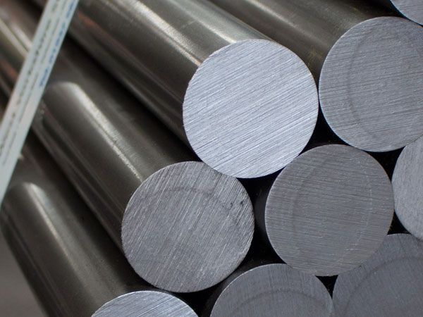
INCONEL (nickel-chromium-iron) alloy 600 Round bars (UNS N06600/W.Nr. 2.4816) is a technological material that is heat and corrosion resistant. Excellent mechanical properties of the alloy combine high strength with ease of production.
An Inconel fastener, often known as a fastening, is a piece of hardware that mechanically connects or fastens two or more things. Inconel round bars are often used to create non-permanent connections, which may be disassembled and rebuilt without causing damage to the connecting components. For their weight, Inconel 600 round bars are very robust. Round Inconel 600 bars have a melting point of 1413 degrees Celsius and a density of 8.47 grammes per centimetre (2580 degrees Fahrenheit).
Cylindrical Inconel 600 bar characteristics
In Inconel 600 round bars, you can find nickel 72.0, chromium 14.0–17.0, iron 6.00–10.00, carbon 0.15, manganese 1.00, sulphur 0.015, silicon 0.50, and copper 0.50. It also exhibits tensile strengths of 95,000 Psi and 655 MPa as well as yield strengths of 45,000 Psi and 310 MPa.
Round Inconel 600 Bars’ features
Inconel 600 round bars were extremely powerful and have great corrosion resistance. The presence of sulfuric and hydrochloric acids is advantageous for this material. Amazing Mechanical Capabilities at High Temperatures The resistance to stress corrosion cracking is good.
Application of Round Inconel 600 Bars
Round Inconel 600 bars are applied throughout a wide range of industries. They execute their jobs in an environment where they must be able to handle the extreme pressure and do well under stress. Some of the industries that use these round bars are trains, petrochemicals, pulp and paper, oil and gas, and pulp and paper. Based on nickel, Inconel 600 is an alloy. Round bars have been utilised in a wide variety of applications, including the heaters, stills, bubble towers, and condensers used in the processing of fatty acids; the same evaporator tubes, tube sheets, and flaking trays used in the production of sodium sulphide; and the machinery used to handle biogenic acid in the manufacturing of paper pulp.
Inconel vs Hastelloy: Inconel is a corrosion-resistant, oxidation-resistant alloy that performs well in high-temperature, high-pressure conditions, Hastelloy is a nickel-molybdenum alloy with a high melting point. It is available in a variety of grades, the bulk of which are nickel chromium molybdenum alloys.
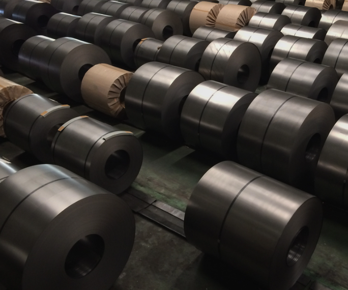
In order to comply with the government’s COP26 commitments, the Ministry of Steel has requested the stakeholders to develop a time-bound action plan to cut emissions in the steel industry. A government report states that whereas the iron and steel sector generally generates 8 percent of the world’s yearly carbon dioxide (CO2) emissions, it makes up 12 percent of the total CO2 emissions in India. The COP26 climate change summit’s accords require the Indian steel industry to considerably decrease its emissions.
Prime Minister Narendra Modi said at the COP26 global climate summit in November 2021 that India will reach its goal of having net zero emissions by the year 2070.
In a recent meeting, Steel Minister Ram Chandra Prasad Singh “urged the stakeholders to develop a time-bound action plan and work together to reduce emissions from the steel industry in line with the commitments made by the Government at COP26.”
In addition, the current situation, the next steps for promoting the switch to green steel, the various strategies and technologies that the steel industry can use to produce green steel, and the levels of technological readiness were discussed.
At the meeting, participants also discussed using green hydrogen to produce iron and carbon capture, utilization, and storage (CCUS) technologies to reduce emissions.
“Reputable academic institutions, research laboratories, and steel companies have submitted joint collaborative R&D project proposals for the development of new alternative processes and technologies to address the sector’s challenges…(and) The ministry will provide financial assistance under the R&D Scheme for the Financial Year 2022-23.
Read More :
How does India intend to decarbonize the steel sector? : As one of the most significant materials for engineering and construction, steel is used in many aspects of our life. Steel is one of the most important components of modern society.
ISMC (Indian Standard Medium Channel) Weight chart: Mild steel channels are U-shaped steel structures that can be described by the size and thickness of their sides. Mild steel channels have two parts: the flange at the bottom and the web at the top. The flange is the horizontal part at the bottom, and the web is the vertical part at the top.
As one of the most significant materials for engineering and construction, steel is used in many aspects of our life. Steel is one of the most important components of modern society. The steel sector is currently one of the three industries that produce the most carbon dioxide. Therefore, steel businesses across the globe face an increasing decarbonization challenge to decrease their environmental and economic carbon footprint.
Currently, India is the world’s second-largest steel producer. India plans to treble its steel production by 2030, according to its National Steel Policy from 2017. Multiple analyses indicate that by 2050, the amount of steel utilized could increase by a factor of several. In order to meet expanding domestic and international demand, India’s steel production will significantly increase during the next few decades.
The majority of carbon emissions from steel factories may be readily extracted from their process- and off-gas. Thus, they are suitable candidates for carbon capture. This collected carbon can be sold back into the market, allowing manufacturers to maintain low costs while making significant progress toward global net-zero targets, or it can be stored for the long term. Captured CO2 from steel mills can be used as a raw material. For instance, it can be used with water and steel slag to produce construction materials. Tata Steel will establish India’s first carbon capture plant for blast furnaces in 2021. This facility will catch and reuse 5 tonnes of CO2 per day.
Use of Syngas
Syngas is typically produced by converting coal to gas, and their primary usage is to generate power. Using the syngas may be more efficient than directly burning the original fuel. Syngas can be utilized to produce an effective reducing gas that can be used to produce DRI. This method is utilized by the JSPL steel factory located in Angul, Odisha.
Use of Green Hydrogen
Hydrogen-based green steel production can make India less reliant on coal imports and more self-reliant. Investing in blast furnaces now will ensure that imported coal will be required until at least the middle of the century, if not longer. By replacing coal with hydrogen produced from renewable energy (dubbed “Green Hydrogen”), the majority of carbon could be eliminated from the industrial sector. If coal were replaced with hydrogen at the current price, steel prices would increase. This disparity is anticipated to narrow over the next few years, and it may perhaps disappear by 2030. On the one hand, carbon and carbon-emission pricing could increase the cost of utilizing coal, while on the other hand, the costs of renewable electricity, hydrogen, and steel production using hydrogen-based processes will decline. With Reliance and Adani entering the green hydrogen industry, India might become a leader in the production of green steel.
Use of Solar Power
To achieve the temperatures required for conventional steel production, a great deal of fossil fuel energy is employed. In India’s major steel-producing states, such as Odisha and Chhattisgarh, where there is abundant sunlight, solar energy can replace fossil fuels. Currently, solar electricity is the cheapest form of energy in India.
Through Adopting Energy Efficiency Measures
The steel business is subject to global competition, therefore producing steel using less energy can be a competitive benefit in addition to reducing energy use. Process industries can save expenses by utilizing energy more efficiently, and energy-saving solutions can be advantageous for a company. Utilizing more efficient technology, recovering energy throughout the manufacturing process, enhancing the efficiency of energy conversion, and ensuring that operational methods are as efficient as possible are ways to improve energy efficiency.
Through Recycling Steel Scrap
Reusing steel reduces the amount of ore that must be extracted. Additionally, it conserves energy and reduces greenhouse gas emissions. Steel can be recycled as often as necessary without losing its useful properties. This transforms a resource that cannot be utilized repeatedly into one that can. Recycling steel uses around half the energy required to produce new steel, resulting in fewer carbon emissions.
All of the above must be included in India’s carbon emission reduction plan. The PHD Chamber of Commerce and Industry is committed to assisting stakeholders and the Central and State Governments in their efforts to decarbonize business and industry. Minerals & Metals Committee and Power, Renewable & Alternate Energy Committee of PHDCCI have been working to prioritize policy reforms and promote sustainable development goals in order to achieve the ambitious decarbonization & RE target and assist the government in constructing an Atmanirbhar & Green Bharat.
Read More :
ISMC (Indian Standard Medium Channel) Weight chart: Mild steel channels are U-shaped steel structures that can be described by the size and thickness of their sides. Mild steel channels have two parts: the flange at the bottom and the web at the top. The flange is the horizontal part at the bottom, and the web is the vertical part at the top.
Now consider what this means in terms of pressure rating:
At a temperature of 600 degrees F°, the class 150 flange can sustain only 140 psi (as per the rating chart below) The class 300 flange (which is larger and stronger but has the same hole size) can sustain 570 psi at 600 degrees F°. Finally, a class 2500 flange of the same size can withstand 34 times the pressure of a class 150 flange, with a rating of 4730 psi at 600 F°!
Scroll down to see the rating table that pertains to your flange (this depends on the material of the flange, as flanges with different material grades have different pressure ratings) Determine your piping system’s maximum working temperature (i.e. select one line in the table) Choose a rating based on the expected maximum pressure at that temperature level (i.e. select one column in that line) You’ve now received the required rating! Below are the ASME B16.34 pressure rating charts for the most common flange materials to assist you (carbon, alloy, stainless).
Pressure rating is the highest amount of pressure that a flange can handle as the temperature rises. The ANSI/ASME B16.5 standard lists seven pressure ratings for flanges: 150, 300, 400, 600, 900, 1500, and 2500. The terms “pressure rating,” “class,” “#,” “Lb,” and “Lbs” all mean the same thing when it comes to how a flange handles pressure and temperature (and other equipment like valves, fittings, etc).
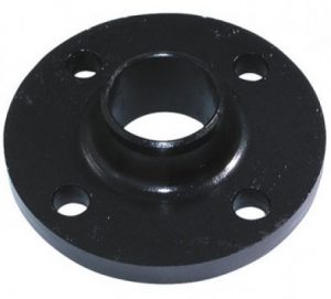
Let’s use an example to make this clear:
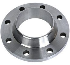
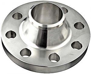
If two flanges have the same bore size, say 6 inches, and the same material, say A105, but different pressure ratings, say class 150 and class 300, the class 150 flange will be smaller, lighter, and less sturdy than the class 300 flange (class 300). This is what the picture shows:
How the Flange Rating System Works
People who are new to the pipe industry frequently have difficulty understanding how flange rating works. Let us first define a flange and the role it plays in the plumbing sector before proceeding with the discussion.
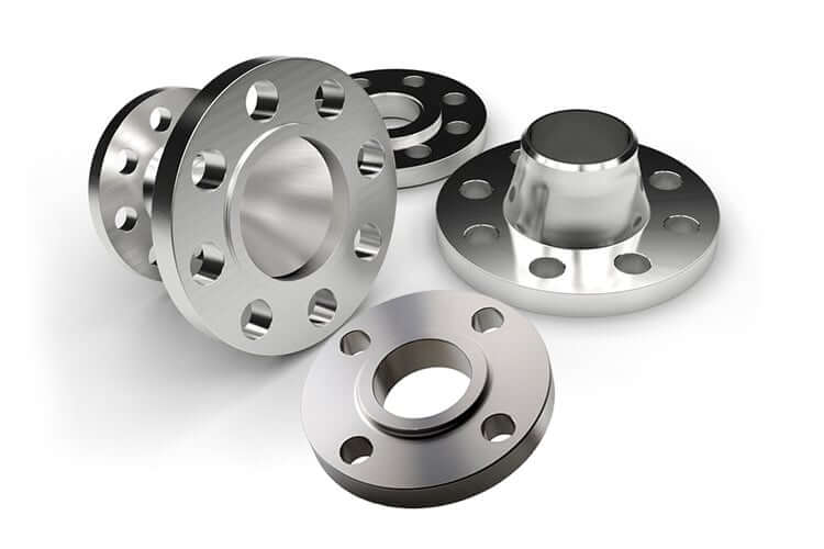
What exactly is a flange and how does it work?
A flange is a piece of equipment that connects pipes, pumps, valves, and other piping components to form a pipeline system. The flange is an important part of the piping system because it allows for easier cleaning, inspection, and modification. Weld Neck Flange, Slip-on Flange, Socket Weld Flanges, Lap Joint Flange, Threaded flange, Blind flange, Orifice flanges, Reducing flanges, and many other types of flanges are available.
What is the flange rating and how does it work?
It’s crucial to make sure that the flanges used in the oil, gas, and petrochemical industries can resist the pressures and temperatures they’re exposed to. Not only is the size of the flanges significant, but so is the rating. As a result, selecting a flange with the appropriate rating ensures that it can endure the pressures of functioning at different temperatures.
The maximum pressure that a flange can withstand at high or increasing temperatures is defined by the class of the flange. Flanges having a higher flange rating or flange class are naturally considered stronger since they can withstand more pressure at higher temperatures.
The ASME B16.5 standard, which applies to flanged fittings and pipe flanges, is the industry standard for flanges. This contains flanges with diameters ranging from 12″ NPS to 24″ NPS.
As a result, as the temperature rises, the maximum allowable pressure falls. With the following example, the notion of flange rating can be readily described.
A Class 300 flange can resist higher pressure than a Class 150 flange because it is made of more metal and can tolerate more pressure. However, a flange’s pressure capability is affected by a number of factors.
Because it is comprised of more metal and can withstand more pressure, a Class 300 flange can withstand higher pressure than a Class 150 flange. The pressure capability of a flange, on the other hand, is influenced by a variety of elements.
The maximum pressure for flanges of classes 150/300/400/600/900/1500/2500 at increasing temperatures (Celsius or Fahrenheit) – in PSI – is shown in the flange rating table.
ANSI/ASME B16.34
ANSI PRESSURE RATING
Temperature (in F°)
150#
300#
400#
600#
900#
1500#
2500#
< 100
285
740
985
1480
2220
3705
6170
200
260
680
905
1360
2035
3395
5655
300
230
655
870
1310
1965
3270
5450
400
200
635
845
1265
1900
3170
5280
500
170
605
805
1205
1810
3015
5025
600
140
570
755
1135
1705
2840
4730
650
125
550
730
1100
1650
2745
4575
700
110
530
710
1060
1590
2655
4425
750
95
505
675
1015
1520
2535
4230
800
80
410
550
825
1235
2055
3430
850
65
320
425
640
955
1595
2655
900
50
230
305
460
690
1150
1915
950
35
135
185
275
410
685
1145
1000
20
85
115
170
255
430
715
Hydrostatic Test Pressure (in Psig)
450
1125
1500
2225
3350
5575
9275
Notes
The maximum pressure for flanges of classes 150/300/400/600/900/1500/2500 at increasing temperatures (Celsius or Fahrenheit) – in bars – is shown in the flange rating table.
ANSI/ASME B16.34
ANSI PRESSURE RATING
Temperature in C°
150#
300#
400#
600#
900#
1500#
2500#
-29 / 38
19.6
51.1
68.1
102.1
153.2
255.3
425.5
50
19.2
50.1
66.8
100.2
150.4
250.6
417.7
100
17.7
46.6
62.1
93.2
139.8
233
388.3
150
15.8
45.1
60.1
90.2
135.2
225.4
375.6
200
13.8
43.8
58.4
87.6
131.4
219
365
250
12.1
41.9
55.9
83.9
125.8
209.7
349.5
300
10.2
39.8
53.1
79.6
119.5
199.1
331.8
325
9.3
38.7
51.6
77.4
116.1
193.6
322.6
350
8.4
37.6
50.1
75.1
112.7
187.8
313
375
7.4
36.4
48.5
72.7
109.1
181.8
303.1
400
6.5
34.7
46.3
69.4
104.2
173.6
289.3
425
5.5
28.8
38.4
57.5
86.3
143.8
239.7
450
4.6
23
30.7
46
69
115
191.7
475
3.7
17.4
23.2
34.9
52.3
87.2
145.3
500
2.8
11.8
15.7
23.5
35.3
58.8
97.9
Notes:
ASTM A105: Long-term exposure to temperatures above 425°C transforms steel’s carbide phase to graphite (this material is not recommended for consistent temperatures above this number).
The ASTM A350 LF6 standard states that it should not be utilized at temperatures above 260 degrees Celsius.
ANSI FLANGE ASTM A350 Gr. LF3, A350 LF6, Class 2
The flange rating chart depicts the maximum pressure for flanges of classes 150/300/400/600/900/1500/2500 at various temperatures (in degrees Celsius or Fahrenheit) – in PSI.
ANSI/ASME B16.34
ANSI PRESSURE RATING
Temperature in °F
150#
300#
400#
600#
900#
1500#
2500#
-20 to 100
290
750
1000
1500
2250
3750
6250
200
260
750
1000
1500
2250
3750
6250
300
230
730
970
1455
2185
3640
6070
400
200
705
940
1410
2115
3530
5880
500
170
665
885
1330
1995
3325
5540
600
140
605
805
1210
1815
3025
5040
650
125
590
785
1175
1765
2940
4905
700
110
570
755
1135
1705
2840
4730
750
95
505
670
1010
1510
2520
4200
800
80
410
550
825
1235
2060
3430
850
65
270
355
535
805
1340
2230
900
50
170
230
345
515
860
1430
950
35
105
140
205
310
515
860
1000
20
50
70
105
155
260
430
ANSI FLANGE ASTM A350 Gr. LF1
The maximum pressure for flanges of classes 150/300/400/600/900/1500/2500 at increasing temperatures (Celsius or Fahrenheit) — in PSI — is shown in the flange rating table.
The maximum pressure for flanges of classes 150/300/400/600/900/1500/2500 at increasing temperatures (in Celsius or Fahrenheit) – in PSI – is shown in the flange rating table.
The maximum pressure for flanges of classes 150/300/400/600/900/1500/2500 at increasing temperatures (Celsius or Fahrenheit) – in PSI – is shown in the flange rating table.
ANSI/ASME B16.34
ANSI PRESSURE RATING
Temperature °F
150#
300#
400#
600#
900#
1500#
2500#
-20 to 100
275
720
960
1440
2160
3600
6000
200
230
600
800
1200
1800
3000
5000
300
205
540
720
1080
1620
2700
4500
400
190
495
660
995
1490
2485
4140
500
170
465
620
930
1395
2330
3880
600
140
435
580
875
1310
2185
3640
650
125
430
575
860
1290
2150
3580
700
110
425
565
850
1275
2125
3540
750
95
415
555
830
1245
2075
3460
800
80
405
540
805
1210
2015
3360
850
65
395
530
790
1190
1980
3300
900
50
390
520
780
1165
1945
3240
950
35
380
510
765
1145
1910
3180
1000
20
320
430
640
965
1605
2675
1050
20
310
410
615
925
1545
2570
1100
20
255
345
515
770
1285
2145
1150
20
200
265
400
595
995
1655
1200
20
155
205
310
465
770
1285
1250
20
115
150
225
340
565
945
1300
20
85
115
170
255
430
715
1350
20
60
80
125
185
310
515
1400
20
50
65
95
145
240
400
1450
15
35
45
70
105
170
285
1500
10
25
35
55
80
135
230
The maximum pressure for flanges of classes 150/300/400/600/900/1500/2500 at increasing temperatures (Celsius or Fahrenheit) – in PSI – is shown in the flange rating table.
ANSI/ASME B16.34
ANSI PRESSURE RATING
Temperature °F
150#
300#
400#
600#
900#
1500#
2500#
-20 to 100
275
720
960
1440
2160
3600
6000
200
235
620
825
1240
1860
3095
5160
300
215
560
745
1120
1680
2795
4660
400
195
515
685
1025
1540
2570
4280
500
170
480
635
955
1435
2390
3980
600
140
450
600
900
1355
2255
3760
650
125
445
590
890
1330
2220
3700
700
110
430
580
870
1305
2170
3620
750
95
425
570
855
1280
2135
3560
800
80
420
565
845
1265
2110
3520
850
65
420
555
835
1255
2090
3480
900
50
415
555
830
1245
2075
3460
950
35
385
515
775
1160
1930
3220
1000
20
350
465
700
1050
1750
2915
1050
20
345
460
685
1030
1720
2865
1100
20
305
405
610
915
1525
2545
1150
20
235
315
475
710
1185
1970
1200
20
185
245
370
555
925
1545
1250
20
145
195
295
440
735
1230
1300
20
115
155
235
350
585
970
1350
20
95
130
190
290
480
800
1400
20
75
100
150
225
380
630
1450
20
60
80
115
175
290
485
1500
20
40
55
85
125
205
345
Read More :
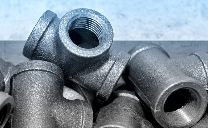
What you should know about forged threaded fittings: Forged Threaded 45-degree Elbows are said to be one of the oldest types of forged fittings that have been used for a long time. When pipes have a smaller bore and diameter, threaded fittings are used to connect them. A pipe with a threaded fitting should have a nominal diameter of around 2 NPS or less.
What is a threaded joint fitting that has been forged?
Forged Threaded 45-degree Elbows are said to be one of the oldest types of forged fittings that have been used for a long time. When pipes have a smaller bore and diameter, threaded fittings are used to connect them. A pipe with a threaded fitting should have a nominal diameter of around 2 NPS or less.
When a Forged Threaded 45-degree Elbow is used, the number of equipment types can be cut down.
By using threaded fittings, the number of joints can be cut down.
A male or female thread makes it easy to connect many different kinds of equipment.
A threaded fitting doesn’t need any special tools to be put in place.
Here are a few important things to remember when putting in forged threaded fittings:
Use a male PVC thread in a female PVC thread at all times. If you did this process backward, the pipe might break.
The thread tape should always be wound in the same direction as the thread. This ensures a safe and durable seal.
Don’t make threads out of hemp. When hemp is put in water, it grows bigger. The pipe could break if this keeps happening.
How forged threaded fittings are used
Always keep in mind that forged threaded fittings can’t be used in high-pressure situations.
So, here are some of the most common ways that Forged threaded fittings are used:
Cooling system for water distribution
Fire hydrants and fire safety, among other things.
Let’s look at a few different kinds of threaded fittings:
There are two main types of elbow fittings: threaded and plain.
90-degree elbow with threads
45-degree elbow with threads
Pipes that change direction by 90 degrees use threaded 90-degree elbows.
Pipes that change direction by 45 degrees need threaded 45-degree elbows.
Threaded Tee Connection Fitting: This fitting turns the main pipe into a 90-degree branch.
There are two kinds of tee fittings.
Equal tee: Both the Branch pipe and the Main pipe are the same size.
Reducing tee: The branch pipe is smaller than the main pipe.
A threaded cross fitting is a joint that connects in four different ways. This fitting has one entry point and three exit points. The flow of things goes in three different directions. Most cross fittings have female threads that make sure connections are secure.
Threaded Coupling Fittings: There are both full and half couplings for these fittings.
Caps with threads: Caps with threads are used to seal the ends of pipes.
Threaded Plug: A threaded plug is used to seal a joint or block it from being seen.
There are three kinds of plugs with threads:
Square plugs with threads
Plugs with a hexagonal head
Plugs with round tops
Threaded Bushing: These fittings have a head in the shape of a hex or hexagon, and they are used to connect different-sized threaded pipes.
Threaded Union: A threaded union is made up of three parts that are all connected to each other. There are mainly two kinds of threaded unions:
Male to Female
Female to Female
A lug nut holds the pieces of equipment together.
Read More :
Differences Between Copper and Beryllium Copper : Copper is a fragile metal, and beryllium copper is used for its superior quality. Beryllium copper gets the highest quality rating out of any copper compound.